SCALP instructions contain no register specifiers which removes one of the greatest problems, namely checking for dependencies between instructions. However SCALP does still have to ensure the correct ordering of instructions, and branches make this a little hard. SCALP also features variable length instructions which complicate matters.
This document describes the SCALP Instruction Issuer Problem. It is organised into three parts:
I hope that this problem may be of interest to asynchronous theorists looking for a real problem to apply their techniques to and also to asynchronous designers who want to compare design approaches. There are parts of this design that I'm not proud of (I'll let you work out which!) and I wouldn't be at all suprised if many of you come up with better solutions. So enjoy and let me know what you think!

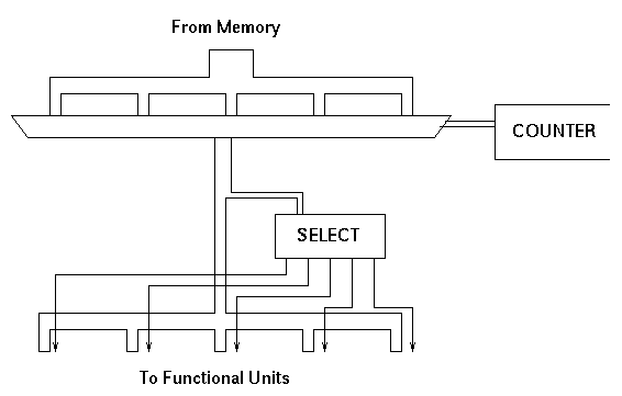
In this arangement, when an instruction group arrives from memory each of its component instructions is considered in turn using a counter and a multiplexor. The functional unit indicating bits are separated off and used to control a four-way select element. The remaining ten bits are connected to each of the four functional units, but under the control of the select element only one of them receives a request signal.
The problem with this solution is that it imposes too much sequentiality. In a parallel processor like SCALP it is essential that no part of the system becomes a bottleneck; the throughput of each stage must be balanced. The memory interface is wide so several instructions can be fetched together and the four functional units can operate in parallel. It is necessary that the instruction issuer can also operate with some matching degree of parallelism.
So this is the problem: to build an instruction issuer that incorporates parallelism.
Note that although the order in which instructions for one particular functional unit must arrive at that functional unit is fixed, the order in which instructions are issued between the functional units may vary. For example, if an instruction group contains five instructions for these functional units
 0   1   2   3   4
F0  F0  F2  F2  F1
then initially instructions 0, 2 and 4 can be issued to functional units F0, F2 and F1 respectively. Subsequently instructions 1 and 3 can be issued.
The boundaries between instruction groups are also unimportant. For example if two groups contain instructions for these functional units
 0   1   2   3   4
F1  F1  F1  F1  F1
F0  F0  F0  F0  F0
then the issuer may choose to issue instruction 0 in the first group to functional unit F0 and simultaneously instruction 0 in the second group to functional unit F1.
A good solution will trade off the performance benefits of these forms of out-of-order issue against their implementation cost.
The incoming instruction groups are stored in what I refer to a "forked fifo"; this is an asynchronous fifo queue whose input is controlled by a single request/acknowledge pair and whose output has separate request and acknowledge signals for each instruction. This arangement means that once an instruction has been issued then it can be acknowledged and removed from the output of the fifo, making the instruction behind it in the next instruction group visible and eligable for issue.
The control is then divided up into one unit coresponding to each of the functional units. These units "watch" the instructions at the front of the forked fifo and when they see an instruction for their functional unit they activate the appropriate switch in the crossbar and send a request to the functional unit.
This arangement is shown in the following figure:
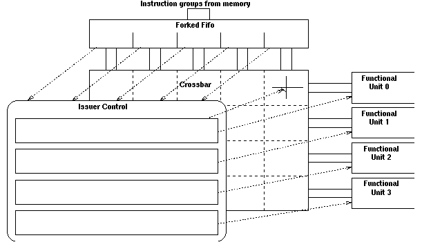
Each functional unit controller can see the following information about each instruction at the front of the forked fifo:
Unfortunately this information is not quite suficient because of the way that the forked fifo works. Consider the following two cases:
 0   1   2   3   4
F0  F1  F2  F3  F0
F0  F1  F0  F1  F2

 0   1   2   3   4
F0  F1  F2  F3  F0
        F0  F1  F2
In the first case the front row of the forked fifo is full. In the
second case the first two instructions from the front row have already
been issed making the first two instructions from the second row
visible. Note that in both cases the instructions visible to the controllers are the same: F0, F1, F0, F1, F2. Consider the controller for functional unit 0. In the first case the correct behavior is for it to issue instruction 0. In the second case the correct behavior is for it to issue instruction 2.
Here is another example:
 0   1   2   3   4
F0  F1  F0  F2  F2
F0  F1  F0  F1  F2

 0   1   2   3   4
F0  F1  F0  F2  F2
F0  F1  F0  F1
Once again the instructions visible to the controllers are the same: F0, F1, F0, F1, F2. Consider the controller for functional unit 2. In the first case the correct behavior is to for it to issue instruction 4. In the second case the next instruction in program order for functional unit 2 is instruction 3 of the second group; an instruction which is not visible yet.
To solve these problems I associate a modulo-3 counter controlled by the request and acknowledge signals with each column of the forked fifo. The controllers see the states of these counters and are able to tell which instructions belong logically before others. I use letters A, B, C to indicate the state of the counter and refer to its value as the "layer" in which the instruction belongs; this is orthogonal to the rows and columns of the crossbar.
The algorithm that the controllers have to implement is then as follows:
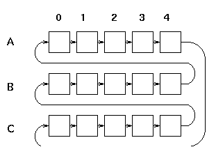
After considering several possibilities I decided that the best implementation is in fact a hybrid sequential / parallel implementation. The principle of operation is this: for each column and each layer a block of logic precomputes what it would do if this instruction and layer were the "current" instruction and layer. These precomputations can all be carried out in parallel. A "token" is then passed between the blocks making them the current block for a brief time. Since the action that must be carried out when the token has arrived has been precomputed the token can progress from block to block very quickly.
The organisation of the blocks and the token's path between them is shown in the following figure:
The internal organisation of each of the blocks is shown here:
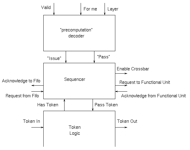
At the ends of the various rows columns and layers things like OR gates are required to merge the signals that may come from several blocks within the structure.
And so to the implementation:
The requirements can be described by this psuedo-STG. The signals has_token and pass_token are 4-phase signals and their rising and falling transitions are shown. The token_in and token_out signals are 2-phase and rising and falling transitions are equivalent.
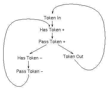
I say psuedo-STG because this STG has some unpleasant properties; it allows the next token to arrive before has_token has been cleared, for example. I know that in my implementation the token has to pass through 14 other blocks, some of which are going to block it, before it gets back here. I therefore choose to ignore some of these problems.
My implementation is as follows:
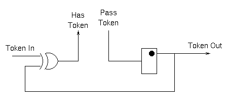
The component on the right is "half a 2-phase toggle"; alternate transitions on the input cause transitions on the output. In can be implemented with a simple d-type flip flop.
Operation is as follows: when no token is present, the input and output and the same so the output of the xor gate is 0. When a token arrives on the input, the xor gate output becomes high asserting has_token. When pass_token is asserted the output is toggled, transmitting a token to the next stage and also inverting the input to the xor gate. This causes has_token to become 0 once again.
Getting the reset behavior correct is important. For all blocks the "half 2-phase toggle" element's internal state must be cleared such that its output is low and the first rising edge of pass_token will cause an output transition. Additionally the block in column 0, layer A must generate an initial token as reset is removed. I do this by adding an extra xor gate in the path from token_out to the xor gate.
As an aside, the reason why the 4-phase implementation was more complex is that it needed acknowledge signals for the tokens. The 2-phase circuit manages without them.
Inputs                     Interpretation               Outputs

Valid   Layer     For_me                                Issue   Pass

X       Previous  X        Can't see the instruction
                           we want; wait                0       0

0       This      X        Must wait and see if this
                           instruction is for me        0       0

1       This      0        This instruction not for me  0       1

1       This      1        For me; issue it             1       0

X       Next      X        Don't worry about this yet   0       1
Unfortunately being an asynchronous system this can't be implemented
with a simple combinational function. We have to worry about glitches
on the Issue and Pass outputs and think about the order in which the
inputs can change. The valid signal is ( request AND NOT acknowledge ). Assume that the AND NOT function is hazard free and fast.
The for_me signal is a bundled data signal that will be set up before valid is asserted and is held until after it is disasserted. While valid is low for_me can glitch.
The layer signals are driven by a counter controlled by the request and acknowledge signals. I arange the counter so that the layer signals change in response to acknowledge rising, which coresponds to valid falling; in fact valid and the layer signals can change at around the same time. This isn't a problem because both valid rising first and this_layer rising first lead to the same sequence of outputs. However it does mean that the circuit has to be hazard free with respect to these changes.
My implementation of the decode logic is as follows:
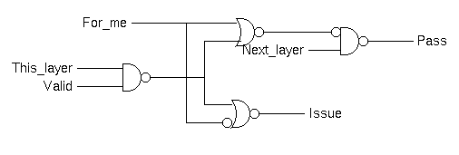
The case of just passing the token is quite simple; when "pass" and "has_token" are both asserted together, assert "pass_token".
Issuing the instruction involves more steps and some questions. For example, at what point should the token be passed on? Can it be passed when issuing starts or must it wait until it has completed? There are similar and important questions about the order in which things can be disaserted.
My solution is described by the following schematic:
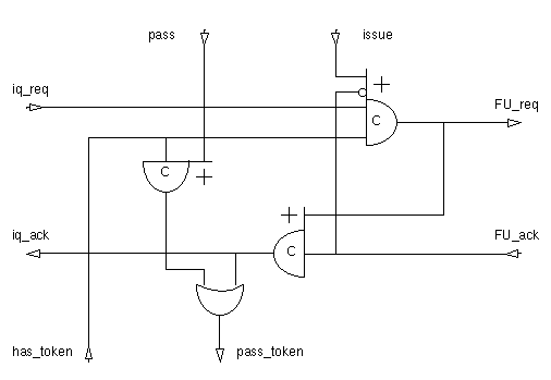
(Note that asymetric Muller-C elements are represented by a gate symbol with extensions to one or both sides. Inputs joining the body of the gate take part in both rising and falling transitions of the output. Inputs joining a side marked with a + or - take part in only that transition.)