
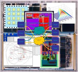
APT research areas
The AMULET3 microprocessor
AMULET3 [1, 2] will be the third generation asynchronous ARM processor. Its predecessors, AMULET1 and AMULET2e, have been fabricated and are described elsewhere.
In designing AMULET3 there is a slightly different design philosophy from the earlier devices; these were primarily designed as low power processors and performance was a secondary consideration. AMULET3 will attempt to retain the high power efficiency of the earlier devices whilst yielding much higher performance. Although we do not expect performance as high as StrongARM (as has been reported elsewhere) we do expect to close the gap between asynchronous and synchronous ARMs significantly. AMULET devices are designed in the same non-process specific techology that ARM Ltd. use; a fair basis for camparison will therefore be ARM9.
AMULET3 has been modelled in LARD an asynchronous hardware design language developed within the AMULET group. This has - and is - providing useful information on the effect of alterations in the microarchitecture of the processor.
The bus structure is more like StrongARM than previous AMULET processors. For example the register bank has been extended to allow up to three simultaneous reads and a method for forwarding results with a minimal penalty within the asynchronous environment has been devised [3]. This also allows out-of-order instruction completion whilst allowing the register state to be recovered in the case of an exception such as a page fault [4].
Features (will probably) include:
- Compatability with ARM "level 4" instruction set
- "Thumb" mode
- 15% fewer cycles/instruction than AMULET2
- Low latency load/store with asynchronous out-of-order completion
- Unrestricted register forwarding
- Branch target prediction and branch fetch suppression
- Very low power "sleep" mode
- Dual ("Harvard") bus interface
- 0.35µm, 3 layer metal process
There is also increasing evidence that asynchronous circuits emit less intense and non-harmonic EMI; AMULET2e provided a practical demonstration of this. AMULET3's EMC properties should therefore be better than an equivalent synchronous device.
The following table contains some performance figures for the processor core. These are based on streams of identical instructions and have been derived from simulations of extracted layout. Note that the influence of memory speed is not factored into these figures; it has been assumed that instructions can be supplied at a sufficient rate. It is likely that the first silicon will be memory limited when running ARM code, although not when using the Thumb instruction set when two instructions are fetched in parallel.
| Instruction | Time | Equivalent frequency | MOV | 7.5ns |
|
ADD | 8.7ns |
|
TST | 7.2ns |
|
LDM! (1st cycle) | 9.8ns |
|
LDM! (subsequent) | 7.7ns |
|
In comparison with the AMULET2 processor core this yields a speedup of about:
| Feature | Improvement | Architecture (CPI) |
|
Cycle time |
|
Process |
|
Total (approx.) |
|
Layout tour
This is a picture of the AMULET3 processor core layout, showing its main features.

The core size is just over 3mm x 1mm. The lower strip is the 32-bit data path, which is all full-custom layout. The upper half primarily comprises blocks of standard cells performing the control functions. At the very top of the picture is the wiring loom interconnecting the control parts of the asynchronous pipeline. The instruction fetch interface is on the left of the picture, the data memory interface is on the right.
At the left hand side of the data path is the prefetch unit. This is dominated by the dense RAM/CAM structure of the branch prediction unit. To the right of this is the PC handling logic and the light-coloured stripe where the instruction is tapped from the datapath. Above this lies the prefetch unit control, internal configuration logic and the (moderately large) Thumb translation unit.
The next unit is the immediate extractor and branch offset adder. These are discernable by the gap in the higher order bits (lower on datapath) and the "spotty" structure respectively. Above these is the main instruction decoder, which is dominated by the controller for the multi-cycle instructions.
In the centre of the core is the register bank with its decoders above and the forwarding logic above them. The reorder buffer is to the right of this unit, and leads into the other register recovery logic which ensures instructions are restartable after memory faults [4]. Some inter-bus multiplexers also lie here.
The barrel shifter is relatively small and lies below the execution control unit. The multiplier is large, with several sparse cross-routeing channels. It protrudes above the datapath to accommodate the shifts to produce 64-bit products. Its control is located above it.
The leftmost two units are the ALU and the data interface. The ALU is mostly an adder which, again, can be descried. Above this the standard cell block contains the various status registers used in mode switching. The data interface is "stripy" as it is required to rotate incoming data for byte alignment, again requiring vertical wiring channels. Its local control inhabits the standard cell area above it.
This page is still developing, as is the processor.
Watch this space for further developments!
References
[1] S.B. Furber, J.D. Garside, D.A. Gilbert - AMULET3:
A High-Performance Self-Timed ARM Microprocessor
Proceedings ICCD'98 (October 5-7)
[2] J.D. Garside, S.B. Furber, S-H. Chung - AMULET3
Revealed
Proceedings Async '99 pp. 51-59 IEEE Computer Society Press - April 1997
- (ISSN 1522-8681 ISBN 0-7695-0031-1)
[3] D.A. Gilbert, J.D. Garside - A
Result Forwarding Mechanism for Asynchronous Pipelined Systems
Proceedings Async '97 pp. 2-11 IEEE Computer Society Press - April 1997
[4] D.W. Lloyd, J.D. Garside, D.A. Gilbert - Memory
Faults in Asynchronous Microprocessors
Proceedings Async '99 pp. 71-80 IEEE Computer Society Press - April 1997
- (ISSN 1522-8681 ISBN 0-7695-0031-1)
Could you use it?
If you have an application which requires significant computing power, low power dissipation and low EM emissions - and you're prepared to take it to silicon - why not talk to us?
The AMULET3 development is supported by the OMI/ATOM project. The designers wish to acknowledge this support from the CEC.